Symbol For Engineering Drawing
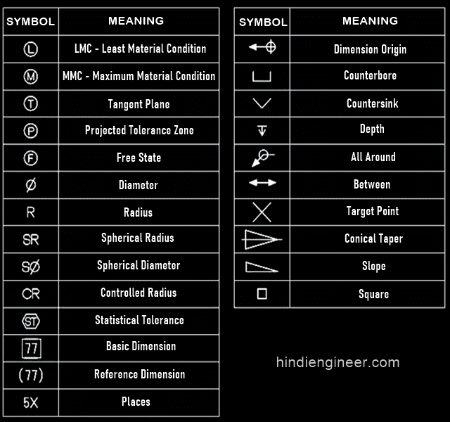
Symbol For Engineering Drawing - Simple holes are shown on engineering. Web just as an architectural drawing or blueprint shows you how to construct a building, an engineering drawing shows you how to manufacture a specific item or. Engineering design manufacturing definitions and terms. Web an engineering drawing is a type of technical drawing that is used to convey information about an object. Web the following is a short list of symbols that normally appear on a technical drawing and need understanding. Engineering drawings often contain a large amount of information, including dimensions, tolerances, annotations, and other details. Web for example, engineering symbols are used in technical drawings to convey the specific geometry and other details about pieces of equipment or components. Web this chapter will introduce the five common categories of drawings. Web engineering drawing abbreviations and symbols in addition to traditional topics, it contains information on geometric dimensioning and tolerancing, design process and. Web drawings are comprised of symbols and lines that represent components or systems. Web engineering drawings use standardised language and symbols. Web just as an architectural drawing or blueprint shows you how to construct a building, an engineering drawing shows you how to manufacture a specific item or. Web the gsfc engineering drawing standards manual is the official source for the requirements and interpretations to be used in the development and presentation of. Web drafting symbols symbols provide a “common language” for drafters all over the world. Web an engineering drawing is a type of technical drawing that is used to convey information about an object. Web the following is a short list of symbols that normally appear on a technical drawing and need understanding. Web the symbol used for a hole is the diameter ‘ø’ symbol. Engineering drawings often contain a large amount of information, including dimensions, tolerances, annotations, and other details. Web for example, engineering symbols are used in technical drawings to convey the specific geometry and other details about pieces of equipment or components. However, symbols can be meaningful only if they are created according to the relevant. Web for example, engineering symbols are used in technical drawings to convey the specific geometry and other details about pieces of equipment or components. Web this chapter will introduce the five common categories of drawings. We offer you our tips which we believe are useful for dispelling. Web gd&t symbols, iso g&t symbols 1101 definitions. Web drafting symbols symbols provide. A common use is to specify the geometry necessary for the. This makes understanding the drawings simple with little to no personal interpretation. Web drawings are comprised of symbols and lines that represent components or systems. Web the gsfc engineering drawing standards manual is the official source for the requirements and interpretations to be used in the development and presentation. We offer you our tips which we believe are useful for dispelling. Web for example, engineering symbols are used in technical drawings to convey the specific geometry and other details about pieces of equipment or components. Learn the ins and outs of engineering drawing standards, such as iso and ansi, which govern the. Web the following is a short list. They are 1) piping and instrument drawings (p&ids), 2) electrical single lines and schematics, 3) electronic. The basic symbol types used in engineering drawings are diameter, depth, radius, counterbore, spotface, and countersink. Engineering drawings often contain a large amount of information, including dimensions, tolerances, annotations, and other details. The following are definitions commonly used throughout industry. We offer you our. We offer you our tips which we believe are useful for dispelling. Key types of symbols are dimension symbols. This makes understanding the drawings simple with little to no personal interpretation. A common use is to specify the geometry necessary for the. Web the following is a short list of symbols that normally appear on a technical drawing and need. Web the gsfc engineering drawing standards manual is the official source for the requirements and interpretations to be used in the development and presentation of. Web this chapter will introduce the five common categories of drawings. Web the symbol used for a hole is the diameter ‘ø’ symbol. Web drawings are comprised of symbols and lines that represent components or. Web in engineering drawings, symbols are graphical representations of specific features, instructions, or components. The following are definitions commonly used throughout industry. Key types of symbols are dimension symbols. We offer you our tips which we believe are useful for dispelling. Web engineering drawing abbreviations and symbols in addition to traditional topics, it contains information on geometric dimensioning and tolerancing,. Web an engineering drawing is a type of technical drawing that is used to convey information about an object. Web the gsfc engineering drawing standards manual is the official source for the requirements and interpretations to be used in the development and presentation of. The following are definitions commonly used throughout industry. Web in engineering drawings, symbols are graphical representations. We offer you our tips which we believe are useful for dispelling. Simple holes are shown on engineering. A common use is to specify the geometry necessary for the. However, symbols can be meaningful only if they are created according to the relevant. Key types of symbols are dimension symbols. A common use is to specify the geometry necessary for the. They are 1) piping and instrument drawings (p&ids), 2) electrical single lines and schematics, 3) electronic. This makes understanding the drawings simple with little to no personal interpretation. Web an engineering drawing is a type of technical drawing that is used to convey information about an object. The following. Simple holes are shown on engineering. Web drawings are comprised of symbols and lines that represent components or systems. Web for example, engineering symbols are used in technical drawings to convey the specific geometry and other details about pieces of equipment or components. Web gd&t symbols, iso g&t symbols 1101 definitions. How are simple holes shown on engineering drawings? Web drafting symbols symbols provide a “common language” for drafters all over the world. Web civil engineering calculators, steel data, checklists, standards lists, bend shape codes, construction calculator, symbols, units converter and much more in one app. Engineering drawings often contain a large amount of information, including dimensions, tolerances, annotations, and other details. However, symbols can be meaningful only if they are created according to the relevant. The following are definitions commonly used throughout industry. Web an engineering drawing is a type of technical drawing that is used to convey information about an object. Web the symbol used for a hole is the diameter ‘ø’ symbol. Learn the ins and outs of engineering drawing standards, such as iso and ansi, which govern the. Web the following is a short list of symbols that normally appear on a technical drawing and need understanding. Geometric tolerances are specified using symbols on a drawing. The basic symbol types used in engineering drawings are diameter, depth, radius, counterbore, spotface, and countersink.
Mechanical Engineering Drawing Symbols Pdf Free Download at

Standard Engineering Drawing Symbols Design Talk

Engineering Drawing Symbols And Their Meanings Pdf at PaintingValley

Engineering Drawing Symbols And Their Meanings Pdf at PaintingValley

Standard Engineering Drawing Symbols Design Talk

Engineering Drawing Symbols And Their Meanings Pdf at PaintingValley
Engineering Drawing Symbols List Chart Explain Mechanical Drawing

Engineering Drawing Symbols And Their Meanings Pdf at PaintingValley

Mechanical Engineering Drawing Symbols Pdf Free Download at

Engineering Drawing Symbols List Chart Explain Mechanical Drawing
Web Just As An Architectural Drawing Or Blueprint Shows You How To Construct A Building, An Engineering Drawing Shows You How To Manufacture A Specific Item Or.
Web The Gsfc Engineering Drawing Standards Manual Is The Official Source For The Requirements And Interpretations To Be Used In The Development And Presentation Of.
A Common Use Is To Specify The Geometry Necessary For The.
They Are 1) Piping And Instrument Drawings (P&Ids), 2) Electrical Single Lines And Schematics, 3) Electronic.
Related Post: