Leader Line In Engineering Drawing
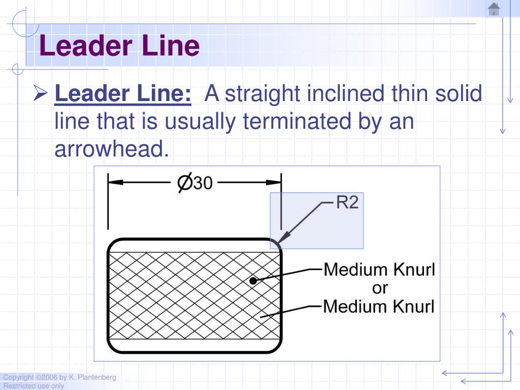
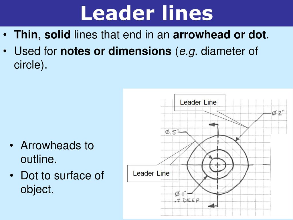
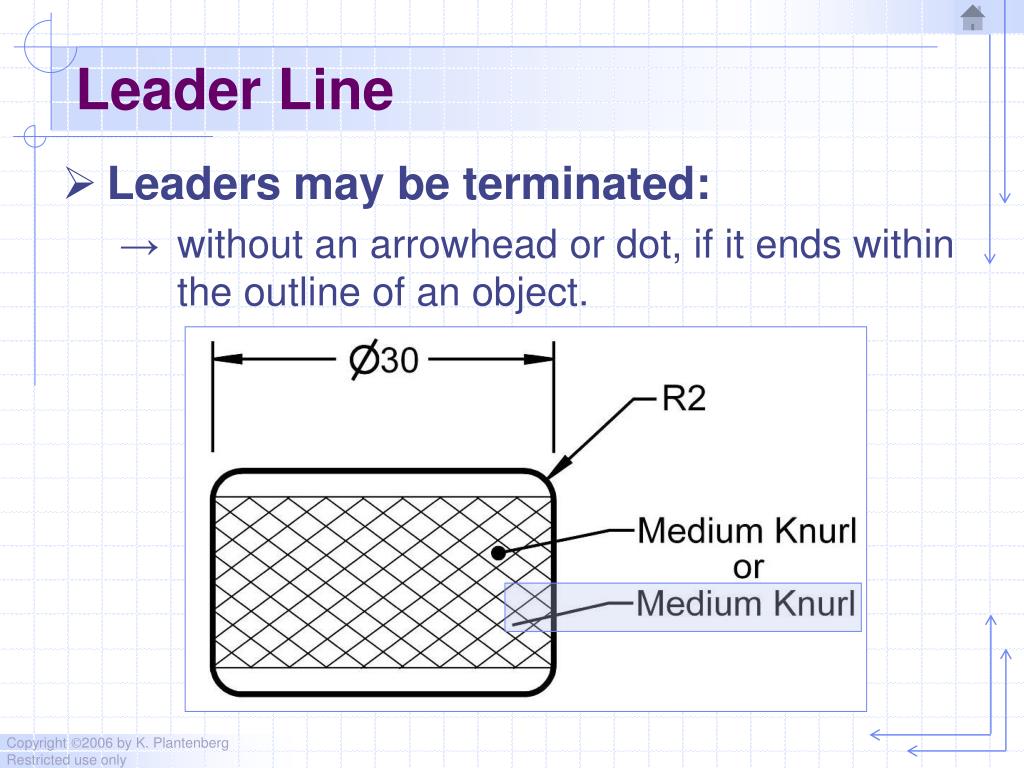
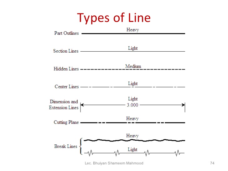
Leader Line In Engineering Drawing - Web standard engineering drawing line types. Leaders are used to indicate information about hole diameters, radii, and other information that occurs as a specific location or on a particular surface on the drawing. All three line types are drawn continuous and thin. However, extension lines can cross other extension lines or visible lines. The extension lines for dimensioning should run from the outlines without leaving a gap and extend beyond the dimension lines. Web dimension, projection, leader, hatching lines. They are used to connect parts or symbols, to indicate distances and dimensions, or to draw attention to an item in the drawing. This statement is particularly true in regards to technical drawings. These lines are solid and has no break in them. To ensure clear and consistent communication, drawings must adhere to. Lines on mechanical engineering drawings This type is also used to draw outlines of adjacent and revolved. Web leader line — a thin, solid line with arrow drawn under an angle & indicating the feature with which a dimension or note is associated. They are typically utilized when pointing to notes, labels, or callouts that provide additional information about a particular object or detail. The main features of leader lines. Dimension, projection, leader, hatching type lines must be drawn thin and continuous. The extension lines for dimensioning should run from the outlines without leaving a gap and extend beyond the dimension lines. The leader line itself should be a continuous thin line (see this post on linetype definitions ). Web dimension lines should not cross extension lines or other dimension lines. Web leader lines, how they are used on blueprints. The extension lines for dimensioning should run from the outlines without leaving a gap and extend beyond the dimension lines. To prevent confusion in the interpretation of hidden edge lines, you must apply certain standard techniques in drawing these lines. They typically originate from a note, label, or callout and connect to the object or area being referenced. In these. Web a leader line is a thin line on a design or blueprint that is used to connect a dimension line with a particular area or point on the drawing. To prevent confusion in the interpretation of hidden edge lines, you must apply certain standard techniques in drawing these lines. A leader may also be used to indicate a note. They are used to connect parts or symbols, to indicate distances and dimensions, or to draw attention to an item in the drawing. These lines are solid and has no break in them. Leader lines are straight or curved lines that have an arrow or dot at one end and are used to point to specific features or annotations in. However, extension lines can cross other extension lines or visible lines. Dimensions make use of dimension lines, extension lines and leader lines. Web leader lines are used to direct attention to specific areas or features on an engineering drawing. Leader lines are used to mention a specific note to a feature on a drawing, as well as to direct dimensions,. To prevent confusion in the interpretation of hidden edge lines, you must apply certain standard techniques in drawing these lines. They are used to connect parts or symbols, to indicate distances and dimensions, or to draw attention to an item in the drawing. The extension lines for dimensioning should run from the outlines without leaving a gap and extend beyond. Leader lines are very useful for placing text or a dimension in a limited space on a drawing and for adding specific notes pertaining to the drawing. Basic conventions and applications for leader lines and reference lines — part 23: Lines on construction drawings — part 24: A variety of line styles graphically represent physical objects. There are several acceptable. Leader lines are straight or curved lines that have an arrow or dot at one end and are used to point to specific features or annotations in a drawing. To prevent confusion in the interpretation of hidden edge lines, you must apply certain standard techniques in drawing these lines. Leaders are drawn as straight lines, but they must be drawn. Dimensions make use of dimension lines, extension lines and leader lines. Leader lines are straight or curved lines that have an arrow or dot at one end and are used to point to specific features or annotations in a drawing. A leader is a thin line used to connect a dimension with a particular area (figure 24). Web a leader. Web dimension, projection, leader, hatching lines. Lines on mechanical engineering drawings Web extension lines begin 1.5 mm from the object and extend 3 mm from the last dimension line. Web the continuous thin line is the most frequently used line type on engineering drawings. A leader is a thin line used to connect a dimension with a particular area (figure. Dimension, projection, leader, hatching type lines must be drawn thin and continuous. Limits of size — the largest acceptable size and the minimum acceptable size of a feature. A leader is a thin line used to connect a dimension with a particular area (figure 24). To prevent confusion in the interpretation of hidden edge lines, you must apply certain standard. Web dimension, projection, leader, hatching lines. Types of lines include the following: Web a leader line is a line that establishes a connection between a graphical representation of an item and some text. They are used to connect parts or symbols, to indicate distances and dimensions, or to draw attention to an item in the drawing. They typically originate from a note, label, or callout and connect to the object or area being referenced. The leader line itself should be a continuous thin line (see this post on linetype definitions ). Web dimension lines should not cross extension lines or other dimension lines. Lines on construction drawings — part 24: A variety of line styles graphically represent physical objects. There are several mark types that can be displayed at the end of leader lines. You have heard the saying, “a picture is worth a thousand words”. Basic conventions and applications for leader lines and reference lines — part 23: Web leader line — a thin, solid line with arrow drawn under an angle & indicating the feature with which a dimension or note is associated. Web leaders are lines in engineering drawings that provide a clear visual reference to other elements in the drawing. The main features of leader lines. This type is also used to draw outlines of adjacent and revolved.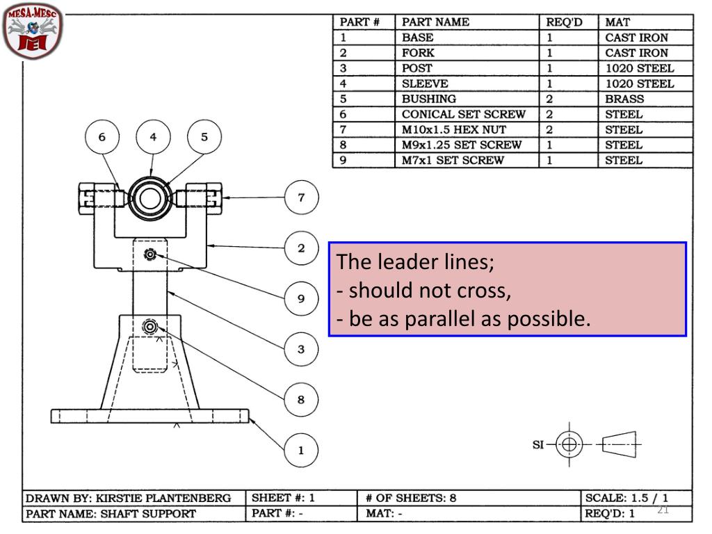
PPT ENGINEERING DRAWING PowerPoint Presentation, free download ID
PPT Chapter 2 Dimensioning PowerPoint Presentation, free download
Top more than 122 leader line in engineering drawing latest

Leader Line In Engineering Drawing Hidden / Line conventions in

leader line in engineering drawing winterbeachweddingoutfit

leader line in engineering drawing fordtransitconversionvan
Line Conventions Line Conventions Introduction to Engineering DesignTM
PPT Chapter 2 Dimensioning PowerPoint Presentation, free download
Engineering Drawing 8 Tips to Improve Engineering Drawing Skills (2023)
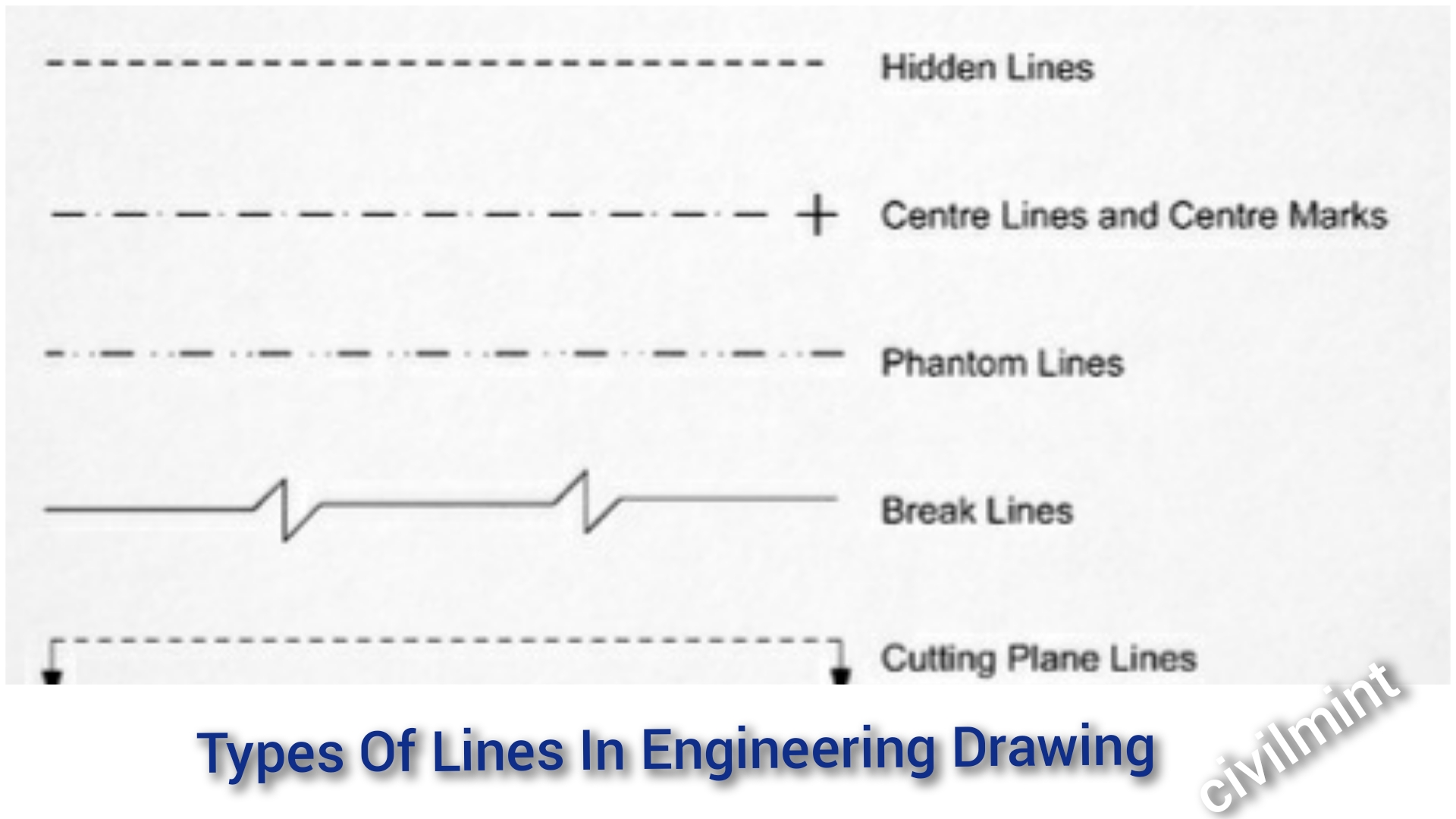
27 Different Types Of Lines In Drawing Pics Drawer Ri vrogue.co
Here Is The List Of Cases Where The Continuous Thin Line Will Be Used:
Limits Of Size — The Largest Acceptable Size And The Minimum Acceptable Size Of A Feature.
This Statement Is Particularly True In Regards To Technical Drawings.
Leaders Are Used To Indicate Information About Hole Diameters, Radii, And Other Information That Occurs As A Specific Location Or On A Particular Surface On The Drawing.
Related Post: